Posted on

How To Build A Mini DIY Powerwall with Maker Batteries

12v-20ah-kit

The 1s6p modules from Maker Batteries are great for building large capacity batteries. At just over 20AH each, a single series chain of modules can create a large 20AH battery pack. In this tutorial I’m going to assemble a small 12V 20AH pack, but you can build a larger 24V, 36V or 48V pack with these same instructions by simply adding more cells in series.

Step 1: Measuring each module’s voltage

To start, I’m going to lay out all of my modules and measure their voltages. They should all be within a couple hundredths of a volt. They were checked at the factory and again before shipping, but this is just a sanity check right before we build the battery to triple check that all of our cell modules are good.

measuring-voltage

Step 2: Laying out the cell modules

For these 6p straight modules, the number of different possible layouts is fairly limited. You don’t have as much creativity as with the triangular modules. The two major layouts are either straight packing or offset packing, demonstrated in the two pictures below.

packing-orientation


Straight packing will give you a narrower but longer battery, while offset packing will make a wider battery with less total volume. This is because offset packing is more efficient by leaving less space between the cells. It also gives you twice as much surface area to apply the hot glue (each cell touches the next row in two places instead of one).

The difference between straight and offset packing doesn’t seem like much on such a small battery like this 12V pack, but when you get up to larger batteries like the 13 module 48V20AH battery kit below, offset packing can make a big difference in the length of your final battery.

A 48V20AH battery kit showing cell modules in offset packing

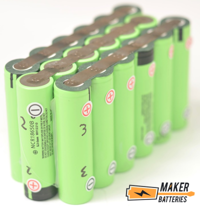
Regardless of the type of packing you go with, remember that you’ll need to place every other module upside down in the pack so that you can easily solder the cell modules in series. Your pack should look like this, depending on the voltage:

more-cell-layouts

Now you can go ahead and glue your cell modules together. Use hot glue liberally and make sure you’ve got a nice strong connection between cells. These packs start to get heavy as you add more modules, so make sure you’ve got a good glue joint to keep them together. If the glue joint happens to fail while you’re working on the pack, just shoot some more glue in the spaces between cells. Be careful not to short the pack later on with the metal tip of the hot glue gun though!

hot-gluing

Step 3: Labeling the cell modules

Next, label your cell modules so that while you’re working you can easily see which end of the cells is positive and negative, as well as which cell module is which. I like to add the positive and negative stickers included in the Maker Batteries kit to the cells, and then write the cell module numbers onto the cells themselves. You can skip the stickers if you just want to write “+1”, “-1”, “+2”, etc onto each cell.

labels

Remember that the end of the cell with the green paper insulation is the positive end (anode). That’s also the cell with the black bands on the heat shrink wrapping. These green Panasonic 18650B cells also conveniently have the + and – signs printed on the sides, though they are pretty small and don’t stand out, which is why I like to add the stickers.

Step 3: Tinning the cell modules

Now we are almost ready to begin soldering our modules together. To prepare for this though we’ll need to tin our cell modules. Tinning is the practice of heating something and applying solder to it. This pre-soldered, or tinned, surface will more easily accept whatever we will be soldering to it next (which in our case is another nickel strip).

On our cell modules we want to make a connection between each individual cell, so that’s where we are going to tin our modules: on the nickel strip between the cells. Start by turning your pack over to the side where you can see the +1 module and the -2 module terminals right next to each other, like in the photo below.

tinning1

The process I used to tin the nickel strip on the modules above is this: apply heat from a good, adjustable temperature soldering iron to the point between the cells for about a second, followed by solder applied directly to the point between the soldering iron and the nickel strip. It’s ok to touch the solder to the soldering iron. Leave the tip of the soldering iron there for about one more second until you see the solder blob spread out and blend into the nickel strip. Now remove the soldering iron.

Using good quality 60/40 lead solder will help make this process easier. The lead solder isn’t very healthy to breathe but it solders beautifully. Just make sure to work in a well ventilated area. Open a window and use a fan to blow the air away from your face and workstation. Just make sure the air isn’t blowing your nickel strips around which could potentially cause a dangerous short if they land in the wrong place.

Here’s an illustration of how the tinning process should look. Notice that the soldering iron spends no more than a couple seconds in contact with the cell module. Though this is a different cell module, the idea is the same.

This is a different battery but the tinning is the same

Step 5: Cutting your nickel strips

Your nickel strip roll will need to be cut into short sections of about 3/4″ or 2 cm long. Cut a few at first to double check that the size is correct. I generally just eyeball it and don’t use a ruler; the exact length isn’t critical. Just make sure they aren’t so short that you can’t easily solder them and aren’t so long that they extend past the nickel strip on both modules.

Use an ordinary pair of scissors to cut the nickel strips into shorter pieces. If you find that you are getting a bit of a bend at the end of the nickel strip, just push the corner flat onto your table to bend it back so it is straight.

If you are using offset packing, you might find it easier to cut your nickel strips into parallelograms instead of straight rectangles. This way your edges will line up with the nickel strip already welded to the battery cells. See the illustrated diagram below in Step 6.

Step 6: Soldering the nickel strips

The process of soldering the nickel strips should be done fairly quickly in order to avoid heating up the battery cells. The whole process should last about 2-3 seconds at most, though you can get probably get it down to under 2 seconds once you get the hang of it.

This is where the chopstick, tooth pick, popsicle stick or other piece of wood is going to come in really handle. The basic process I use for soldering these nickel strips is this:

  1. hold chopstick in my mouth (for easy reach when transferring to my hand)
  2. place nickel onto module so it overlaps the solder blobs I already tinned
  3. hold soldering iron in one hand and solder in the other
  4. place tip of soldering iron on edge of nickel strip to heat it while touching solder to iron and nickel strip
  5. merge the pre-tinned solder blob on the module into the new solder blob I just applied to nickel strip
  6. simultaneously during solder merging, drop solder and pick up chopstick
  7. use chopstick to hold down nickel strip then remove soldering iron – wait 5 seconds until cool.how-to-solder

It sounds complicated but it’s a really smooth 2-3 seconds once you get the hang of it. Basically, hold the nickel strip with the soldering iron while adding fresh solder then hold the nickel strip down with a chopstick until it cools. The end result looks like this:

soldering-gif

You’ll need to make all of your series connections between +1 to -2, and then flip the battery over to work on the other side. That’s where we’ll make the next connection between +2 to -3. For our battery, that will be the last series connection, since we only have 3 modules. If you were making a 24V battery though, you’d have 6 series connections total (connecting 7 modules). I like to do all of the connections on one side of the battery first, and then turn the battery over and complete the series connections on the other side of the battery. When you’re working with big 36V and 48V batteries, it means you do a lot less flipping of the battery that way.

series-connection

When you are performing these series connections you must be extremely careful that you do not short circuit your battery. This can happen by accident if you dropped a piece of nickel strip in the wrong place, or if it simply moved a bit while you were soldering it. For example, if you’ve already completed the series connections between +1 and -2, then flip the battery over to work on the connections between +2 and -3, any conductor that bridged the terminals between -1 and +2 would cause a large spark as it short circuited your battery. If that happened for just a split second, things would probably be fine, though your battery cells wouldn’t be happy about it. If something heavy gauge fell on those connections though and the connection remained constant, your cells would quickly overheat and could begin venting smoke and other gases. You want to avoid this situation so be very careful while working to not let anything short circuit the terminals of your modules.

After you’ve finished soldering all of your series connections, perform a sanity check by measuring the voltage from your -1 terminal to your highest + terminal, in this case the +3 terminal on this 12V battery. You should see your total pack voltage, which on this 12V battery is about 10.575V on these partially discharged cell modules. If you aren’t getting a voltage that is the sum of your cell modules, you must have missed a connection somewhere. Go back and double check that you’ve soldered all of your connections correctly.

Step 7: Adding on your BMS

Now we are ready to add the Battery Management System (BMS) to our battery. I generally like to place the BMS on the end of the pack so that it doesn’t add a lump on the side of the pack.

You can either hot glue it directly to the edge of the pack, or you can take the smaller strip of foam that came with your kit and cut a patch to sit between the BMS and the pack. The foam will add a little more shock protection if you’re using the battery in a situation that will see a lot of movement or vibration such as on an electric bike. If the battery will be stationary most of the time though, simply gluing the BMS down is perfectly fine.

bms1

You’ll notice in the photo above that I’ve gone ahead and tinned the strip of nickel on the +3 terminal of the pack. That is because next we’ll need to attach the positive end of the discharge cable. You can either leave your discharge cable the length it is, or you can cut it back to make it shorter. If you’re making it shorter, trim the thick red discharge cable coming from the yellow XT-90 connector to whatever length you’d like. Make sure to lay it out the way you plan to have it exit the battery to ensure you have enough cable slack to make it all the way out. In this example I’m just going to leave it the same length.

bms2

Strip the cable back far enough to expose a length of wire that can be soldered all the way along the positive terminal of the battery spanning the 6 cells in the last module. A helping hands device comes in very handy at this stage to help hold the wire. Be extremely careful not to let the wire touch anything but the +3 terminal or you could create a short circuit. Because the individual strands in that wire can now become unwieldy, I like to solder along the length of that exposed wire, tinning it and keeping it from unraveling. A helpful tip is to do this in stages as you slide off the silicone insulation. Instead of pulling it off all at once, pull it off about half way, tin the exposed wire, then continue pulling the insulation progressively further while tinning the wire each time. You’ll get to the end and have a nicely tinned wire by the time you pull the insulation all the way off.

Now you can go ahead and solder the red discharge wire onto the +3 terminal (or whichever is your highest # terminal on a larger battery). Again, helping hands come in really useful here. The best method is to tin the wire at increments that match the tinned spots on the wire. Next, while the helping hands hold the wire in place, solder the very tip of the wire to the last spot on the +3 module, in between the last two cells. Next, solder a spot closer back towards the base of the wire. Soldering closer to the base of the wire now will keep you from accidentally heating up the first solder joint enough to cause it to flow and release. Now go along and solder each of the individual locations along the length of the wire to the nickel strip as shown below.

bms3

Once you have the positive discharge wire soldered onto the last module, go ahead and solder the thin red positive charge wire onto the same location. You can even solder it right on top of the thick red positive discharge wire.

bms4

Now you’ll need to solder on the BMS’s thick black wire to the -1 terminal. No matter what voltage battery you are building, this thick black wire goes on the -1 terminal. You’ll likely need to trim it back to whatever length is necessary for your battery. The process of soldering it on is exactly the same as the thick red wire you just did previously, except that it will go on the -1 terminal.

bms5

Next you’ll need to solder on the thin balance wires from the BMS. On the BMS I’m using here, all four wires are white. Generally the first wire will be black, and that will be the -1 wire. You can solder that one on first straight to the -1 terminal. If it’s easier you can solder it directly on top of the thick black wire you just soldered previously. Continuing, the next wire in the line of thin balance wires will be the +1 wire, which goes on the +1 terminal of module 1. The next wire is +2, and the last wire in our case is +3. Since we have a 3s battery, we only have 4 wires. A 10s battery will have 11 balance wires and a 13s battery will have 14 balance wires. There’s always one more wire because the first module gets a wire soldered to both the -1 and +1 terminals.

bms6

The last wires you’ll have to deal with are a set of two wires exiting the BMS. These are for adding a switch. If you wanted to add an on/off switch to your BMS you could add it here by connecting the two wires with a toggle switch. Connecting the two wires and completing that circuit turns on the BMS, while disconnecting the two wires and breaking that circuit turns the BMS off. This could be helpful if you plan on leaving the battery dormant for a long time without using it as it’s a handy way to ensure the battery is off. Otherwise, it’s not really a necessary feature. I’m just going to solder these two together and add a piece of heat shrink. This way my BMS is always ‘on’ and ready to go.

bms7

Depending on the model of BMS in your kit, your two wires might come as a loop. If that’s the case, just leave them the way they are if you don’t need a switch, and if you do want a switch then simply cut the wire and solder the two sides onto a toggle switch.

tape-1

Now that we’ve taken care of all the wires, it’s time to tape everything down. I like to use kapton tape, a non static, heat resistant tape. You can use electrical tape too but I don’t like how it gets gummy and isn’t as strong as kapton tape.

tape-2

Just tape down all your wires so that they are flush with your battery and won’t vibrate or chafe on any of the nickel strips.

This is another good time for a sanity test to ensure everything is correctly connected. Measure the voltage at your charge and discharge connectors to ensure you’re getting the correct pack voltage for your partially charged pack. You can insert your digital multimeter probes directly into your yellow XT90 discharge connector to measure the voltage there. For your charger connector, it’s better to take the extra connector that came in your kit and plug it into the charge port. But first make sure the two bare wires on the end are spread out and not touching, otherwise they can short and fry your BMS. Now you can measure the voltage of your charge connector as well. As long as both are giving you the correct pack voltage then you’re golden. If not, double check all of your connections to find where something isn’t correctly connected.

check-voltage2

Step 8: Sealing your battery

Your kit comes with both foam and heat shrink tubing for sealing up your battery. If your battery will be sitting in one place its whole life then you might not need the foam. It’s there for applications like electric bicycles and other uses where the battery will see a lot of motion, vibration and generally live an active life. If you don’t need the foam, skip to the heat shrink section. For the rest of you, start with the foam.

Lay your battery out on the foam sheet with the paper backing still on. Wrap the foam around your battery to ensure that it’s the right size. If it’s too big, trim some off with a pair of scissors.

foam1

Once you’ve got your foam down to the proper size, remove the yellow backing and wrap the foam around the battery. To cover the ends of the battery, cut a couple pieces of foam off of the second strip of foam supplied in the kit. Remove the paper backing and stick those pieces onto the ends of the battery.

foam2

Now that your battery is all nice and cozy in its foam shell, you’re ready to add the heat shrink. Start with the piece that is wider and slide it around the widest part of the battery. You want about 3/4″ or 2 cm extending on either side of the battery. This overlap will shrink down and hold the sides of the battery, keeping the shrink wrap firmly in place. If there is too much overlap then it won’t shrink down all the way and you’ll be left with wavy edges that can be annoying to cover. Be careful not to cut off too much though. Err on the side of caution and leave it a bit long if you’re unsure. You can always go back and trim the edges back after you’ve shrunken the heat shrink, it’s just a tad bit trickier.

shrink-1

At this point you can use either a heat gun on a low setting or a strong hair dryer on its highest setting. Just don’t turn your heat gun up too high because you can actually melt heat shrink with a strong heat gun. Apply even heat around the heat shrink until it’s completely shrunken around your battery.

shrink2

Next, slide your second, thinner piece of heat shrink along the battery. This time, make sure you’ve got only about a 1/2″ or 1.5 cm of overlap on each side, since the heat shrink has less room to shrink this time. On this piece of heat shrink, I like to start by shrinking the ends first to ensure they get a good wrap on the edges of the battery, then move towards the middle. Try to spread the heat around though and shrink all the sections equally instead of one section and then another.


shrinkgif2

Lastly, apply your logo so that everyone knows that this is a Maker Battery that you built yourself!

dsc_0051

And that’s it, congratulations! You’ve just built your very own lithium battery! What are you going to use it for? Have a cool project you’re working on? If you document your project and want to share it with us, we might feature it on the community projects page to inspire others. Drop us a line and let us know what you built!

Posted on

How To Build A DIY RC Battery with Maker Batteries

dsc_0125

Building an RC battery with Maker Battery modules is surprisingly easy. Just follow the steps below to build your own RC battery!

Step 1: Measure module voltage

Start by measuring the voltage of all of your cell modules to ensure that they’re all more or less identical. They can be off by a few hundredths, but any more than that might indicate that one or more cells have an issue. This is incredibly rare as these cells are checked at the factory and then double checked before shipping, but this triple check is just one last step to ensure that you’re building a top quality battery.

check-voltage

Step 2: Layout your modules

Now you’ll begin your module layout. This will determine the final size and shape of your battery. For most applications a simple linear pack is preferred. If you have a specific battery box that you’re trying to fit your battery into then you might want to get a little more creative with your arrangement.

Generally speaking there are two different straight layout methods: straight packing and offset packing.

packing

Straight packing with result in a narrower yet longer battery, while offset packing is a bit wider yet smaller overall volume. This is because offset packing is a more efficient use of space, leaving less dead air space between the battery cells.

For this tutorial we are going to use straight packing to give us a narrower yet longer battery, but the same steps apply for either method so feel free to use offset packing if you’d like.

When you arrange your cells, make sure you set them up like in the picture above with alternating sides facing up. This will make it easier to perform your series connections later on.

gluing

Now go ahead and hot glue your modules together into the correct orientation. Use a decent amount so you have a good connection, but you don’t have to drown your modules in glue either. These are fairly light weight packs so there isn’t a lot of stress on them from their own weight.

Step 3: Label your modules

You can use the + and – stickers in your Maker Battery kit and/or a marker to label the positive and negative ends of your modules as well as to number the cells. These module numbers will help you keep track of the modules later on when you’re connecting the balance wires. These stickers and labels aren’t 100% necessary, but they can be a nice help when you’re performing the critical series connections. I recommend not skipping this step.

labeling

Step 4: Tinning the modules

In order to solder your cell modules together you’ll first need to tin them. For this process you’ll need two things to ensure good tinning: a good 60W or higher adjustable temperature soldering iron and some quality 60/40 lead electrical solder. Don’t skimp on either. A decent soldering iron can cost $15 and good solder another $10. They’re both worth it. You want to spend as little time heating the cell modules as possible and to do that you need a strong soldering iron that can transfer heat quickly. A weak soldering iron has to sit on the nickel for a long time, which ends up transferring all the heat to the cells. You want just a couple seconds of contact.

tinning-gif

To tin the nickel, touch the tip of your soldering iron to the nickel in between the cells and then touch a piece of solder to the point between the soldering iron and the nickel. You’ll see the solder melt and then within another second begin to blend into the nickel strip. At that point you can remove the soldering iron and move to the next point.

Make sure that you’re soldering on the point in between cells and not directly on top of them. The nickel will heat and tin faster in between cells and that point will also keep the heat as far from the cell as possible.

tinning1


Step 5: Cutting the nickel strips

Now find your roll of nickel strip and open it up. Be careful not to let it get away from you and short circuit your battery terminals.

Cut the first few pieces of nickel strip to approximately 3/4″ or 2 cm in length. You don’t need to measure them out exactly; just eyeball it. They should be long enough to span from one solder blob to another on two consecutive modules.

cutting-nickel

You can use any ordinary pair of scissors to cut the nickel. Depending how you hold the nickel when you cut it, you might find that you get funny corners that turn up at a sharp angle. If this happens, just push the corner against the table to flatten it back down. It’s not a major problem, but the sharply bent corner can sometimes catch on your gloves and cause you to accidentally drag the nickel away from where you intend to place it. It’s more of a problem on the backside of the battery once you’ve already done the first set of series connections. At that point it’s easier to accidentally cause a short circuit on the backside of the battery.

When you cut the nickel strips, you’ll probably notice that they make a slight arc from the shape of the roll. I like to place the nickel strips on the modules with the arc facing down like a rainbow. This keeps the two ends on the solder blobs. If you do it the other way and place the nickel strip down like a bowl it may rock oddly.

Step 6: Soldering the nickel strips

Below you can see the wiring diagram (or nickel strip diagram since we aren’t using wires yet) for the 5s RC battery pack we are making. It is very important that you do these series connections correctly. It’s quite easy to accidentally lay a piece of nickel strip on the wrong connection and cause a short circuit, so pay attention and double check before you lay down each piece of nickel.

When you solder the strips, the name of the game is just like during tinning: try to spend as little time heating the modules as possible. The whole soldering operation should take about 2-3 seconds, though you’ll get it down under 2 seconds with some practice.

This is also where that chopstick, popsicle stick, tooth pick, matchstick or other piece of wood is going to be used. The soldering procedure I use is as follows:

  1. hold the chopstick in my mouth (easier to reach when switching it to my hand)
  2. put the nickel strip onto the module so it overlaps the solder spots I previously tinned
  3. hold the soldering iron in my right hand and solder in my left hand (switch if you’re a lefty)
  4. place the tip of the soldering iron on the edge of the nickel strip to heat it while contacting the solder to the soldering iron and the nickel strip
  5. merge the module’s pre-tinned solder blob into the new solder blob that I just put on the nickel strip
  6. simultaneously while merging the solder blobs, drop the solder and pick up the chopstick with my left hand
  7. use the chopstick to hold the nickel strip down while removing the soldering iron and hold until coolsolderinggif

You’ll want to solder the first two series connections between +1 and -2 and then the second series connections between +3 and -4. However, that’s only two strips of nickel for each series connection. Each strip of nickel can handle about 7.5A and so to get our full 30A current carrying capacity we need four strips. So to get four strips we will simply solder two more strips right on top of the connections we already made. Each connection will be two sets of two stacked nickel strips, as shown in the photo below.

soldering1

After you’ve finished this side of the battery, you’ll need to turn it over and work on the back side. That’s where you’ll connect the “gaps” that we left on the top side of the battery, such as from +1 to -2 and +3 to -4. Be very careful though that you don’t complete any connections that are already completed on the other side of the battery. Look at the wiring diagram at the top of Step 6 again to see which connections you need to make. Notice how if a connection is made on the top side of the battery, it is left open on the bottom and vice versa. This way we are always wiring the modules in series. Your final connections should look like this:

cell-layout-gif

Step 7: Adding the wires

wires1

Now we’ll add the discharge and the balance wires to the battery. Let’s start with the discharge wires on our yellow XT90 connector. You’ll need to strip back about an inch or so (2.5 cm) from the insulation on the red positive wire and tin the wire with solder. I find that a set of helping hands makes this much easier.

wires2

Next you’ll simply solder that red discharge wire onto the pre-tinned spots on your last module’s positive terminal. In this battery, that’s the 5+ terminal. Again, helping hands comes in pretty handy here. (Get it? Sorry…)

wires3

Continue the same way with the black discharge wire. Strip it, tin it, thens older it onto the -1 terminal of your battery. No matter how many modules you have in series, the black discharge wire always goes on the -1 terminal.

wires4

Once you’ve finished with the discharge wires, we can move on to the balance wires. I like to start by simply taping the entire balance wire bundle to the side of the pack, that way I can keep it nice and organized. You can use simple electrical tape, but I prefer kapton tape. It only costs about a buck more, but it’s stickier, easier to work with, non static and heat resistant. It simply works great for battery building and it’s what the professionals use.

wires5

Start with the red wire and solder it to the positive terminal of the highest numbered module you have, which is the 5+ terminal in this case. You can solder it directly onto the thick red discharge wire if that’s easier. Then simply work backwards, taking the wire next to the red wire and soldering it to the positive terminal of each successively lower module. If you’ve done it correctly then the second to last wire will go on the +1 terminal and the last wire will go on the -1 terminal.

wires6

Now is a good time to double check that you are getting the proper voltage at your discharge connector. These batteries are pretty hard to mess up, but if you aren’t getting the expected voltage, just double check your connections and make sure you soldered all the wires and nickel strip in the right places. Also, remember that you won’t get your full pack voltage yet because these cell modules are only partially charged. You should get the sum of however many modules you have in series.

check-voltage-2

Assuming everything checks out, go ahead and tape up all of your wires so they lay flush against your battery and won’t vibrate or work themselves loose over time. Again, I like to use kapton tape here but you can also use electrical tape.

taping

Step 8: Sealing the battery

This is the last step: heat shrinking the battery. You’ll find two pieces of heat shrink in your kit, one should be a bit wider than the other. Start with the widest piece and slide it over the longest dimension of your battery. You want an overhang of about 1/2″ or 1.5cm on the sides. If you used straight packing like I did here, you’ll likely need to trim your heat shrink just a bit so you only have 1/2″ or 1.5cm of overlap on the sides. The heat shrink will come a bit wider to accommodate other layout styles.

shrink1

Now use either a hair dryer on its highest setting or a heat gun on a lower setting to heat the shrink tube evenly. Hair dryers of 2,000W seem to work well, while lower powered ones may work, but can take longer.

I like to start on the two exposed ends and shrink those first to make sure they grab around the sides of the battery well, then I go back and heat the middle. Turn the battery around while heating to ensure that all parts of the heat shrink actually shrink down and squeeze the battery.

shrink3

Next, take the second piece of shrink tube and slide it down over the entire battery. Again, make sure you’ve got about 1/2″ or 1.5 cm of overlap on each end. Now repeat the heat shrinking process and evenly heat the shrink tube, starting at the ends, until the entire shrink tube is wrapped around the battery.

shrink4

If you wind up with any pieces on the ends that didn’t shrink down all the way and stick out like wrinkled folds, you use a pair of scissors to cut those back. Then reheat the spot to smooth the edge.

The final step is simply to add your sticker to the outside of the battery in order to show everyone that this is a Maker Battery and you built it yourself!

dsc_0104

Congratulations, you’ve finished building your battery! Good luck with your project and have fun!

Posted on

How to Build a 48V 10AH battery with Maker Batteries

dsc_0063

These instructions demonstrate how to use triangular Maker Battery modules to build a battery. In this case, we are going to be building a 48V 10AH battery, but you can use these instructions to build any voltage and capacity battery you’d like simply by altering the number and placement of cell modules.

Step 1: Measuring cell voltage

Before you can start laying out your battery, you want to do one last double check to ensure that all of your battery modules are at the same voltage. They are checked at the factory, but this is just one final test before you begin. Simply measure the voltage of each module with a digital multimeter. You should see that all of your cell modules are basically identical. Any difference of more than a few hundredths of a volt would indicate that one cell group might be slightly discharging itself. This is incredibly rare, but you should still check for it before you assemble your pack. In this case, all cells measured out at about 3.502V. Anything between about 3.49 and 3.51 would be fine for these cell modules – as long as they are all within a few hundredths of a volt. These modules were all within a few thousandths – perfect!

measuring-voltage


Step 2: Cell module layout

Cell layout is where you have the most freedom to be creative and build any size or shape of battery you’d like. These triangular cell modules lend themselves really well to interesting shapes and geometries. In this walk-through we are going to be building a simple 48V (13s) 10AH battery using 13 cell modules wired in series, but you can use more or less cell modules to create any voltage battery you’d like. This is the orientation that I’ll be using in this walk-through:

13s-layout-1

There are many possible layouts to achieve all sorts of interesting geometries. Just remember to think about how you’ll connect your cells when you lay down the nickel strips. Also, if you’re using the Maker Batteries kit with supplied heat shrink, know that if your battery is too much wider than this layout the heat shrink won’t fit. You have enough room to do a 4-cell-wide pack using the included heat shrink. The format we’ll be using in this tutorial is a slightly small, yet longer, 3-cell-wide layout.

After you’ve decided on your layout, you’ll just need to hot glue your cell modules together into whichever shape you chose. I like to glue the modules together into larger groups of four modules, and then glue those together. You can also just glue them together one at a time. Whatever is most comfortable for you.

Step 3: Label your cells

Next add your positive and negative stickers to help you keep your orientation while you’re working on the battery. Just remember that the end with the green paper insulation gaskets is the positive end of the cell module, while the bare end (red and silver) is the negative end, and apply your stickers accordingly.

dsc_0025

I personally like to follow up the stickers with a written cell number. You can also skip the stickers and just write “+1”, “-2”, etc. Whatever feels most comfortable for you. The numbers help me ensure that I’m connecting the correct cells when I get to the next step.

dsc_0026


Step 4: Tinning the nickel triangles

Now it’s time to take out your soldering iron. You’ll want to use a good quality, adjustable temperature soldering iron. Something of at least 60W should be perfect. The cheap little beginner soldering irons in the 20W-40W aren’t great because they don’t generate enough heat and also lose their heat quickly. This means that you have to spend much longer trying to transfer heat to the nickel, which ends up heating the actual cells. The whole point of this operation is to transfer as little heat to the cells as possible. It sounds counter-intuitive, but a hotter soldering iron will help us heat the actual cells less because we can spend less time touching the nickel with the soldering iron.

You’ll also want to make sure you’re using a good rosin core electrical solder. I prefer 60/40 lead solder. It’s toxic, so don’t breathe in the fumes, but it gives the best solder connection and flows nicely. If you try to use the cheap solder that comes with your soldering iron, it’s just not going to work well. Spend $10 and get some good lead electrical solder.

Let’s start at the beginning of our battery. The negative end of #1 is going to be the negative terminal of our whole battery, so we’ll skip that for now. Instead, we’ll move to the first series connection we have on the top side of the battery, which is the connection between +2 and -3, shown in the diagram below.

first-series-connection

Before we can solder this connection, we’re going to tin the nickel triangle. Tinning means heating up the metal first with the soldering iron, then adding a bit of solder until it appears to merge with the metal, and then removing the heat. This bonds a blob of solder to the nickel triangle and makes it easier to solder something else to the triangle.

where-to-solder

When you solder to these triangles, you want to try to avoid soldering directly on top of the cells. Instead, solder in the areas between cells. These ‘between’ areas with nothing behind them will heat faster which gives you a better solder joint, and will also keep you from passing the heat directly onto the cells.

This is a different battery but the tinning is the same

The points that you choose to tin the nickel triangles will depend on how many pieces of nickel strip you’ll be soldering next to each other. When possible, two pieces of nickel strip side by side are better, but sometimes you’ll only have room for one piece. In this first connection, I’m going to solder two pieces of nickel next to each other so I’ll tin the nickel triangle in two places on each of the triangles.

tinning-triangles


Step 5: Preparing the nickel strip

Now you’ll need to unroll your nickel strip and begin cutting the first few pieces. In this orientation, I’ll need pieces that just under an inch long, approximately 2 centimeters. It’s not super critical and I never break out my ruler to make sure they’re all the same, I just eyeball it and cut the nickel strip as needed.

Start by cutting out 4 pieces of nickel strip for this connection. A pair of scissors is all you need, the nickel is fairly soft. Don’t use your good sewing scissors though – any pair from your junk draw will work.

You might notice that you get a funny, turned up corner when you cut the nickel, depending on how you hold it when cutting. If this happens, just bend the corner back down. It won’t hurt anything, but it can get caught on your gloves or other things when you’re laying it on the battery and that could cause an issue if a nickel piece slips and causes a short circuit.

Next, take a look at the strips of nickel you just cut. They probably have a slight arc in them, right? That’s because they’re fresh off the roll. You can try to flatten them but they’ll probably never be perfectly flat, which is just fine. When you put them on your battery, just put them with the arc facing down, so it’s like a rainbow and not a bowl. That way the two ends are making contact with the nickel triangles. When you hold the piece of nickel strip down during the soldering process it will become flat.

Step 6: Soldering the nickel strip

This is the most critical of all steps and will define the quality of your battery. You want to take your time here. Go slow and ensure that you’re making good quality solder connections.

This is also potentially the most dangerous part of battery building, because this is where you begin increasing the combined voltage of the battery modules and are working with many exposed contacts. Again, go slow and just pay attention to what you’re doing. As long as you think about each connection you’re making and ensure it is correct, you’ll be fine.

This is also the time to double check you don’t have any random bits of metal laying around your table or any jewelry/tools that could fall on the battery and cause a short circuit. Keep your nickel strips off to one side while you’re working so they don’t interfere with your battery.


soldering-1


Now go ahead and begin your first series connection by laying down a piece of nickel strip between the first two modules that you’ve already tinned and then solder one side of the nickel strip to the nickel triangle.

The goal here is to spend as little time heating it as possible. Here’s the procedure I use: Lay the end of the nickel strip over the solder blob you already tinned on the nickel triangle. Now heat the nickel strip with the soldering iron while applying just a bit of solder to the tip of the soldering iron. That bit of solder you added will quickly bond to the nickel strip, and then a second later should merge with the solder blob you already put on the nickel triangle. While the solder blobs are merging, drop the solder from your non-soldering iron hand and pick up your chopstick. Use it to press the nickel strip down and then remove the soldering iron. Gently blow on the soldered connection while still holding it down with the chopstick. After about 3-5 seconds the solder will be hardened and you should be able to lift up the chopstick.

soldering-gif
Different battery, but same soldering technique. Focus on the soldering, not the layout.

This is now a series connection, but it’s not completely finished yet. You put down one piece of nickel strip, but that single piece is only able to carry about 7.5 amps of current. For higher safety and lower resistance, we need to add a few more nickel strips along with that one. I generally put four pieces of nickel strip per connection, giving a maximum continuous current handling of about 30A. If you skimp out and only put one or two, your battery will get much hotter and run less efficiently. Always try to use at least four strips of nickel for each series connection.

There is enough room in this configuration for two strips of nickel next to each other, so go ahead and solder a second nickel strip right next to the first strip. Then after you have two strips, solder another two directly on top of the first two. You’ll follow the same procedure as when you soldered on your first strip. Just lay down a piece of nickel strip on top of the existing piece, add some solder to the end of the new piece and merge the solder blob holding the first strip into the second strip. Sometimes using slightly shorter strips for the piggy-backed pieces can help make the process easier.

Congratulations, you’ve just soldered your first series connection! Now just a dozen or so more, depending on the size of your battery. For this 48V battery we’ll continue on to the next series connection on this side of the battery, which is from +4 to -5, as shown in the diagram below.

second-series-connection

Perform this second series connection exactly like you did for the first one. Tin the center of the nickel triangles, then lay down two strips of nickel next to each other. Complete the first two nickel strips soldering operations, then add another two strips of nickel on top of the first two.

soldering-gif2

Now you should have your first two series connections completed on this side of the battery. Continue with all the remaining series connections on this side of the battery. In the case of our 48V battery layout here, that means we’ll make connections between +6 to -7, then +8 to -9, then +10 to -11, and finally +12 to -13.

third-through-sixth-series-connections

Once you’ve got all of your connections done on this side of the battery it should look approximately like the photo below. Note that the picture was taken before the last series connection was completed, and shows only two nickel strips on the last connection instead of four.

Note: photo taken before second set of 2 nickel strips were soldered between last cell modules

After we’ve finished all of the connections on this side of the battery, we’ll flip the battery over and work on the series connections on the other side.

Now that we are working on the backside of the battery, we need to pay extra careful attention that we are making the proper connections. These series connections will basically “fill in” the connections that were skipped on the first side of the battery we started with. You’ll remember that we didn’t solder between modules 1 and 2, 3 and 4, 5 and 6, 7 and 8, 9 and 10, or 11 and 12 on the first side of the battery. Well, now it’s time to make those connections.

Before you make a connection on the backside of the battery, double check that the same connection is not made on the other side. Just lift the battery up and do a quick sanity check to ensure that you’re placing your nickel strip in the right spot. It’s easy to lose focus for a second and lay down a nickel strip in the wrong spot. But since the other side of the battery is already connected, misplacing a piece of nickel strip now could lead to a short circuit that will quickly heat your nickel strip up to a glowing, red hot beacon of your mistake. You want to avoid this.

backside-soldering1

You’ll notice in the picture above that the battery has been flipped over its end like a cartwheel, not around its long axis like a rotisserie. It doesn’t matter how you flip it; I’m just pointing it out so that you pay attention to the orientation. Now module 1 is on the right and module 13 is on the left.

We’ll complete all of the series connections that are left on this side of the battery, being careful to double check that we are making the right connections. However, you’ll notice on this side of the battery we don’t have room for two nickel strips to lay side by side. This is due to the skinny orientation we chose that has only 3 cells wide. This is fine, it just means that we’ll need to stack four nickel strips on top of each other instead of 2 x 2 like we did on the other side of the battery. Again, using progressively shorter nickel strips can make this easier. It will start to look like layers of a wedding cake as the nickel strips stack up.

Once you’ve completed all of the series connections on this side of the battery, you can go back and tin in the center of the -1 and +13 modules’ nickel triangle, as seen in the photo above. This is where we’ll be connecting our discharge wires in the next step.

Step 7: Adding the Battery Management System (BMS)

Before we add our BMS, we’ll do another quick sanity check to ensure we’ve made our series connections properly. Grab your digital multimeter and measure between the -1 module and the +13 module. You should get the appropriate pack voltage for whatever you are building. We have a 48V battery consisting of 13 series cells, so we’ll get 45.5V (3.5V x 13 modules).

If you don’t get your correct voltage, make sure that you didn’t forget a series connection somewhere.

Now you’ll need to decide where to mount your BMS. It can go pretty much anywhere, but I like to put it on the sides or end of the pack, and not on top of the terminals, just in case the heat shrink ever wore through and caused a short circuit on the terminals. You could cut a piece of foam from the smaller strip of foam in your kit supplies though and place it between the contacts and the BMS if you really have to put it there though.

I generally like to put my BMS on the end of the pack so that the battery has a uniform thickness throughout. I usually stick it closer to the positive end of the pack as well so that the positive charge wire can easily reach the last positive terminal of the battery.

Go ahead and hot glue your BMS to the end of the pack, or cut a piece of foam from the smaller foam strip and place it under the BMS first to add extra padding. If your battery is going to get a lot of shock loading, like on an electric bicycle, then this extra padding can help isolate the BMS a bit more.

On this pack, I’m going to be placing the BMS on the side just before the end of the pack. With only three cells wide, the pack isn’t quite wide enough to fit the BMS at the end without sticking out on the sides.

bms1

Next you’ll need to solder the thick red discharge wire coming from the yellow XT-90 connector to the positive nickel triangle on your last cell module. In this case on a 48V battery, it’s the 13th module’s positive terminal. Before you solder it though, lay out the discharge wires in the orientation you expect them to exit the pack. Then cut the discharge wire to whatever length is necessary. If you want to leave it long, you can just go ahead and solder it without cutting, and that will give you a longer discharge wire.

Strip the end of the red discharge cable and solder it to the last cell module’s positive terminal, then do the same with the thin red wire coming from the charging connector. Just remember that you need to solder these in the center of the triangle, staying away from the corners. Use high heat and a short period of contact between the soldering iron and the nickel triangle.

bms2


Next, you’re going to solder the red wire from the set of many thin balance wires on the other side of your BMS. Depending on your kit, your BMS might not have a single red wire and instead just have a number of white wires followed by a single black wire. Either way, the correct wire from the balance wire connector to solder to the positive terminal of the last cell module is the last wire, as shown in the photo above. To confirm, count the small balance wires and you’ll find that you have one more than the number of cell modules. In this case, I have 14 small balance wires. This is because two wires will eventually get soldered to the first cell module, one on the positive terminal and one on the negative terminal.

Now that you’ve soldered your first balance wire, continue with the rest in the same way. The next small balance wire will be +12, and you’ll likely need to flip over your battery to reach the +12 nickel triangle if you used a similar layout to mine.

bms3


Continue with all of the balance wires until you’ve reached the last wire, a thin black one. This will be soldered onto the negative end of module 1. You may want to wait to solder this until you solder on the thick black wire coming from the BMS. This should also get soldered to the -1 terminal, but will carry all of the current of the battery so this should be a very good solder joint. Measure how much slack you need in the thick black wire and then cut the wire to length. Strip, tin and solder it to the -1 terminal, then solder on that thin black balance wire as well.

bms4

Lastly, you’ll notice that you still have two wires coming off of your BMS. Depending on the model of kit you have, these two wires will either be a loop, or two individual wires that are soldered together at the end, like in the photo below. These are for adding an on/off switch for your BMS, if you’d like. The switch will give you a way to turn off your BMS unit. This could be handy if your system has no other switch, or if you plan on leaving the battery dormant for a long period of time (e.g. months). This specific battery is going to go onto an electric bicycle that already has a system switch, so I’m not going to add a switch here on the BMS. If you wanted to though, any toggle switch that completes this circuit will work just fine as a switch for the BMS.

Because I’m not adding a switch, I’m just going to cover this soldered connection with a piece of heat shrink or tape and then tape the wires down with the rest of the wires onto my battery.

bms6

In fact, now is the time to tape down all of your wires to the pack. Just lay all of the wires out flat and in line with each other and tape them down with either electrical tape or kapton tape. Electrical tape will work, but kapton tape costs only a dollar or two more and is much nicer, since it doesn’t leave any gummy residue and has higher adhesive strength. It’s also won’t build up a static charge.

bms7

Lastly, we’ll do another sanity test just to ensure that everything is correctly wired. Grab your digital multimeter and measure the voltage from your yellow XT-90 discharge connector. You should be seeing your proper pack voltage, which will be a sum of the voltages of the individual modules. Remember, even if your pack is 48V, you likely won’t see 48V on the meter because your cells will come in a state of charge between 30%-50%.

Check the voltage at your charge connector too, but don’t measure directly from the connector. Instead, take the loose charger connector that came in your kit (which you can use later to add to your charger) and spread apart the exposed wires at the end. Make sure they aren’t even close to touching. Now plug it into your charger connector on the BMS and measure the voltage from those exposed wire ends. You should see almost exactly the same voltage as from the discharge connector.

If either of these voltages aren’t your correct pack voltage, this means you have a connection error somewhere. Check all of your balance wire connections as well as your charge and discharge connections. You likely just connected a wire in the wrong order somewhere.

Step 8: Sealing your battery

Now you’ve got a fully functional battery, but you’ll want to wrap it up to protect it. Your kit includes both foam and heat shrink. You should at least use the heat shrink, but the foam is somewhat optional. If your battery will always be sitting in one place, like for use as a home back-up battery, you likely don’t need the foam. However, if your battery will be moving around, like for an electric bicycle battery, you’ll want the foam for added protection. It does reduce the heat dissipation a bit, which is why you can leave it off for stationary applications, but its protective advantages more than outweigh the small efficiency losses from heat dissipation.

foam1

Begin by laying your battery on the foam and wrapping the foam around your battery with the paper still on it. If the foam is too big, cut it down to size with a pair of scissors.

foam2

Then remove the paper backing and roll the foam around your battery. Lastly, cut out a couple pieces from the smaller foam strip and use them to cover the two ends of your battery.

foam3

Now that you’ve got your battery all wrapped in foam, we can use those two pieces of heat shrink you received in your kit.

You’ll want to start with the piece of heat shrink that opens wider, i.e. the one that’s easier to get your leg into than your arm. Slide your battery into this first piece of heat shrink and check that you’ve got about 3/4″ or 2 cm of overhang on both sides. If you have much more than that you’ll end up with edges that don’t shrink down all the way. I recommend cutting the heat shrink back until you’ve got just about 3/4″ or 2cm of overhang. But be careful, because if you remove too much then you can’t add the heat shrink back after you’ve cut it off. You can always cut the heat shrink back after you’ve already shrunk it, though it’s a bit more difficult. So if you are worried about cutting off too much then err on the side of leaving it too long and just trim it afterwards.

shrink1

Make sure your battery is centered in the heat shrink and then use your heat gun or hair dryer to spread even heat over the entire battery. If you’re using a heat gun, start out on a fairly low setting. Some heat guns can get way too hot for heat shrink and end up melting it. For a hair dryer, you’ll need a fairly powerful model. My wife’s 2,000W hair dryer works great! I’ve used a 1,875W model and it worked, but not nearly as well.

shrink-2

On this first piece of heat shrink, I like to start by shrinking the open edges first so they wrap well around the edges of the battery, and then shrink the middle. Notice in the photo above that I have some wavy edges on the ends of the battery. That is an indication that the heat shrink was just a bit too long on either side. You can either heat that and press the wavy parts flat, or trim them back.

Next you’ll use the longer, narrower heat shrink to fully seal the battery. For this piece, I like to have about a 1/2″ or 1.5 cm overlap on each end. The overhang is smaller here because the heat shrink will shrink less than the previous piece, and so the same amount of overhang would often result in too much loose heat shrink after shrinking.

shrink3

One other note: You’ll notice in the photo above that I have cut a slight arc out of the top half of the heat shrink. This is due to the angle at the end of the battery. A straight cut would result in too much heat shrink on the top, so I cut a small arc to remove some of that extra heat shrink. If this is your first time heat shrinking a large battery like this, I recommend not cutting out this arc until after you’ve shrunk the heat shrink and can better gauge where the cut needs to be made.

Again, I like to start the heat at the ends of the heat shrink to make sure they wrap around the edges of the battery and grab on tight, and only then move the heat to the center of the heat shrink to finish shrinking all the way around the battery.

If you are worried that you might have cut too much off and made your heat shrink too short, definitely start shrinking at the ends. Heat shrink mostly shrinks radially, where it has about a 50% shrink ratio. But it will still shrink a little longitudinally with about a 5% shrink ratio. So if it’s short, it will get even shorter. All the more reason to shrink the ends first to ‘lock’ them in and then shrink the middle.

shrink4

The above photo shows what it looks like when the heat shrink was a little too long. You get those wavy parts at the end where the heat shrink kept shrinking but got smaller than opening in the end of the heat shrink, causing it to fold. It’s not a big deal and you can leave it like this, though the hard edges that poke out might chafe at a bag or other battery container. You can also heat the end again and press the folds flat, or cut the folds back and reheat the end to create a smooth edge again.

Lastly, peel off your label and apply it to your battery so that everyone knows that you made this battery yourself!

dsc_0063

And that’s it, you’ve built your own battery using Maker Battery triangle modules! Now what are you going to do with it? If you’ve got a neat project that you documented well, let us know and maybe it will get featured in the community projects section of the site!